1935 - 1936 Ignition Lock Restoration
Let me pass on some tips I have learned from restoring these things. This also can be used for restoring other early Ford ignition switches.
1. There appears to be two different types of locking assemblies (different suppliers?). They look the same from the outside but the inners are very different and not interchangeable but they do have some similar characteristics regarding disassembly.
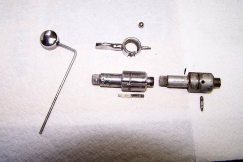
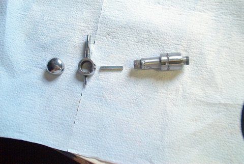
2. First remove the switch box and "inners" on the back of the gear assembly. It is held on to the housing by two screws. Next remove the lock tumbler. In some cases it is held in by a pin and in other cases it is retained by a screw on the bottom. Remove the screw holding the toggle lever tension ball and spring..
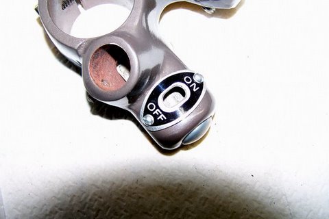
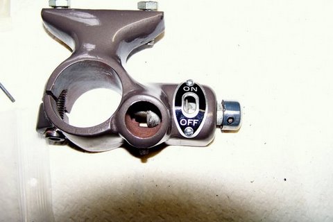
3. Next you need to remove the end cap. However, the cap doesn't like to come off. It is pressed on which means it has to be pulled off. It is difficult to do without harming the cap. The best approach I have found is to remove the "on-off" switch plate. This will allow you to shift the entire locking shaft and cap to the right, enough that you will have a small gap between the cap and the housing. Using a small screw driver as a wedge you can work the cap off. If you damage the cap a replacement one is available for about $20. I am not a real fan of these replacement caps besides being kind of "pricey" (MHO), they are made out of aluminum which is very soft and easily damaged when installing or removing it. However, all is not lost. Usually, with the use of a Dremmel tool you can go a long way in removing pits and scars on the cap. When finished, I just buff and polish. You would be surprised on the results you can have with a little amount of work.
4. A couple of things that you can do to the cap that will make installation much simpler. Thread the cap and the attaching shaft. This will allow you to simply screw on the cap rather than press it on. Another approach is to file down the "ribs" on the locking shaft just enough that it will allow for thumb pressure to push on the end cap. To keep the cap on the shaft I drill a small hole in the cap and then thread the hole to accept a 1/8" set screw. When I install the cap, I just rotate the set screw to the backside of the shaft and everything looks original.. Either way this allows for easy assembly and easy future removal of the cap, if needed.
5. There are two types of on-off toggle levers. One type requires the removal of the "nail" that moves the ignition brush. The "nail" can be removed in several ways. I often use a the claw end of a small brass hammer. The second type does not have a removal nail. The toggle switch and the shifting pin are an integrated casting. To remove this lever requires the removal of a key which can be seen with the end cap removed. Finally to remove the toggle switch you only need to slide the locking rod toward the steering column opening in the housing.
6. The on-off plate is held on by two rivets. The rivets don't like to come off. Usually you end up shearing them off. To make life simpler, I drill and tap the two holes for the use of a #4 screw. This allows the use of a machine screw which looks very similar to an original rivet except for the slot. You gotta be looking hard to spot the difference.
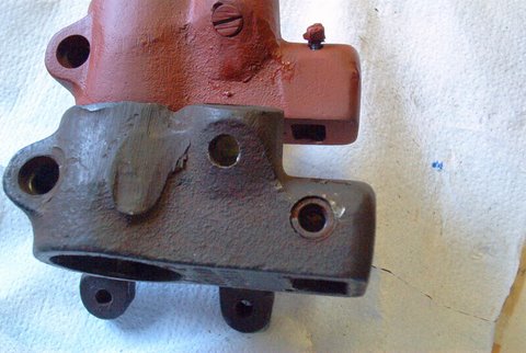
7. Painting- '35-'36 Ford "standard models" are black. The '35 deluxe models are Metallic Taupe. The '36 deluxe are Benton Grey (early models) and Rustic Brown (late models with woodgrain dash).
8. When you finally put things back together spend a few minutes cleaning up the two brass contacts on the plastic plate that attaches to the back of the switch assembly. I use some 280 grit wet and dry paper to clean off the carbon residue. Too often these contacts are over-looked and result in "mysterious" hard starting. scenarios.
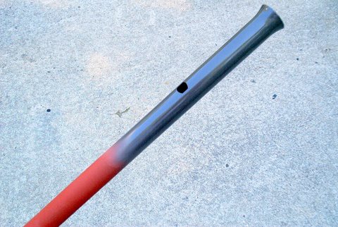
9 Installation of the ignition on the column tube itself can be tricky. Often the steering tube has been damaged with various dents over the years and subsequently these dents were repaired with body filler. This will work for appearance purposes but too often the "repairs" leave slight rises in the surface that will be rapidly discovered when you slide the yoke on. There are a couple of ways to cope with this. First is to spread the yoke slightly to increase the hole opening (NOTE- don't get carried away with the spreading. If you spread the yoke too much you won't be able to get it to close properly on the column tube) and then use wax paper under the yoke to slide it into position. The second way is to do the tube painting in two steps. Paint the top portion of the column the desired color and leave the bottom portion in prime. Slide the yoke on, lock it into place and then mast off the top part and refinish the bottom part. Actually, there is a third way to avoid all the repair rises and that is to make up a new column from a 1.5" tail pipe tube but that's another story.
Helpful Pictures - Click on a picture for a larger version in a new window.